
The efficiency of fluid transport in heavy-duty environments often depends on the specific mechanics of positive displacement, a field where reciprocating pumps remain a primary solution. Unlike centrifugal alternatives that rely on velocity, these units move fluid by trapping a fixed amount and forcing it through a discharge pipe.
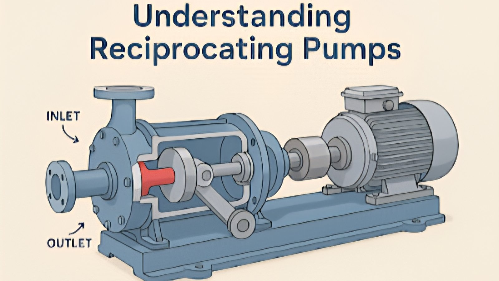
The core operation of a reciprocating pump involves a cyclical process of suction and delivery. During the suction stroke, a piston or plunger moves backward, creating a vacuum that pulls fluid into the cylinder through an inlet valve. As the motion reverses, the increasing pressure forces the inlet valve shut and opens the outlet valve to expel the liquid.
Engineers categorize these machines based on their internal components and the nature of the stroke. The most common varieties include:
Plunger pumps utilize a high-pressure seal that remains stationary while a smooth cylindrical plunger slides through it. These are typically favored for high-pressure applications where durability is paramount.
Piston pumps, where the seal is attached to the moving piston itself. These are frequently found in lower-pressure scenarios but offer high volumetric efficiency for various liquid types.
Diaphragm pumps, which use a flexible membrane to displace fluid. Because the drive mechanism is isolated from the liquid, these are ideal for handling hazardous, corrosive, or highly abrasive materials.
The drive system generally consists of a power source, such as an electric motor, connected to a crankshaft. This assembly converts rotational energy into the linear motion required to drive the internal components. This mechanical transition is what allows for the precise, pulsed flow characteristic of the technology.
While centrifugal pumps are preferred for high-flow, low-pressure tasks, the reciprocating model excels when high head pressure is required. They maintain a constant flow rate regardless of changes in pressure, making them indispensable for chemical injection, oil refineries, and high-pressure cleaning systems.
Maintenance protocols for these systems focus heavily on the valves and seals, which bear the brunt of the mechanical stress. Because the flow is pulsating rather than continuous, many installations include pulsation dampeners to reduce vibration and prevent fatigue in the surrounding pipework.
In the context of Kenyan infrastructure and industrial growth, understanding these mechanical fundamentals is essential for plant managers and site engineers. Whether used in water treatment facilities or specialized manufacturing, the reciprocating pump provides a level of pressure control that remains difficult to replicate with other designs.
Selection of the correct pump type often dictates the long-term operational costs of a project. By matching the specific plunger or diaphragm design to the viscosity and chemical makeup of the fluid, operators can ensure system longevity while minimizing unplanned downtime during critical phases of production.
Comments (0)
Leave a Comment
No comments yet. Be the first to share your thoughts!