

A version of this article appeared on LinkedIn.
How civil engineers interpret a road cross-section involves looking beyond simple lines on a design drawing. A cross-section tells the complete story of the earthworks required to construct a highway by revealing how a proposed road interacts with the existing natural terrain.
Understanding these drawings is one of the most critical skills in highway design. Engineers use them to transform raw topography into safe, durable, and economical infrastructure.
The primary determination an engineer must make is whether a specific section requires a cut or a fill. This decision depends entirely on the relationship between the existing ground level and the proposed formation level.
When the existing ground level lies above the proposed formation level, material must be excavated, meaning the road section is in a cut. Conversely, if the ground level sits below the design level, material must be added to achieve the proper elevation.
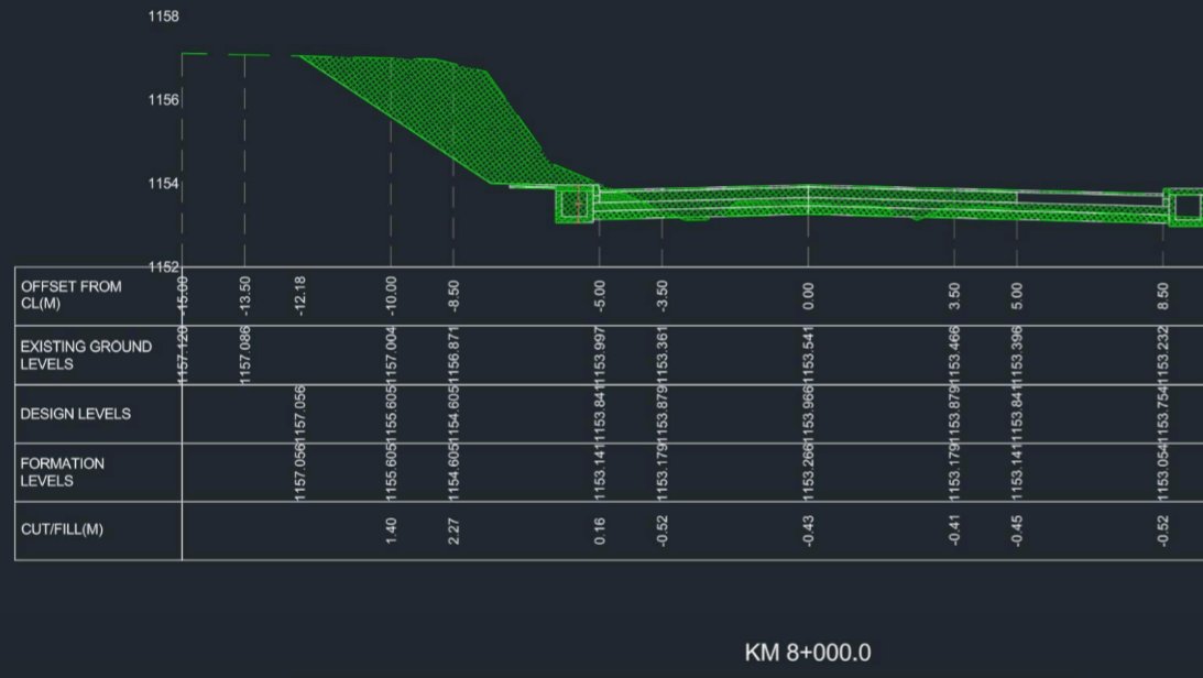
A practical example can be seen in standard highway design documentation at Chainage Kilometer (KM) 8+000. At this specific marker, the road drawing shows a profile that is predominantly in a cut.
The existing ground level sits higher than the design levels across most of the section. Therefore, construction crews must excavate earth to reach the required design levels.
The specific cut and fill values on the drawing confirm this engineering requirement. The data indicates significant cut depths that reach up to 2.27 meters.
Such depths confirm that excavation acts as the dominant earthwork activity for this portion of the alignment. There are still small areas within the same section that display negative values.
These negative values represent fill requirements for the contractor. However, these filling areas remain highly localized and minor compared to the heavy excavation work.
Determining these factors early allows project managers to plan their equipment and labor requirements accurately. Engineers look at specific indicators first when checking a drawing, comparing the proposed formation line against the natural ground line.
Specialized software helps professionals calculate these volumes automatically to save time. Many designers use Computer Aided Design (CAD) platforms to generate these accurate models.
Tools like AutoCAD Civil 3D allow for rapid adjustments to the road alignment. Optimizing the alignment helps balance the total volume of cut and fill material.
Balancing earthworks is vital because hauling soil to or from a site increases construction expenses. In Kenya, managing earthwork costs is a major factor in keeping public infrastructure projects within budget.
Unanticipated excavation can delay timelines and exhaust contingency funds quickly. Proper cross-section interpretation prevents these expensive errors before heavy machinery arrives on site.
Every infrastructure project requires a meticulous review of these design profiles. A single drawing contains vital data regarding slopes, drainage ditches, and structural layers.
Mastering this interpretation ensures that the final road withstands environmental pressures and traffic loads over time. Civil engineering success relies heavily on this precise relationship between drawing analysis and field execution.
Comments (0)
Leave a Comment
No comments yet. Be the first to share your thoughts!